

Arduino Skittle Sorter Machine : 14 Steps - werneralwyet
Introduction: Arduino Skittle Sorter Machine
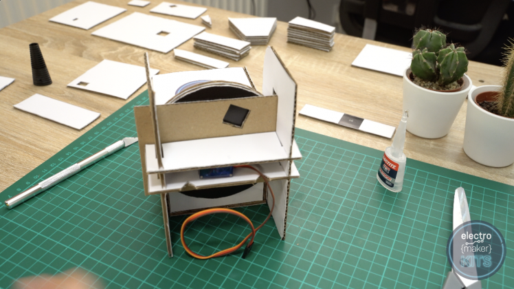
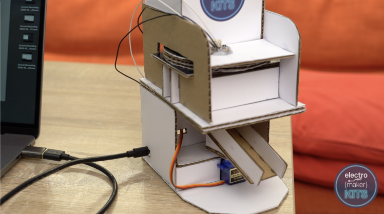
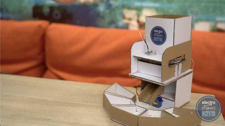
This five-needled Ninepin sort machine is high-powered by an Arduino Nano, two servos and a colour detection mental faculty. Information technology's crafted victimization 3mm thick cardboard. We provide printable A4 templates for you to print and cohere to the cardboard making it easy to cut out yourself.
Check out our full video teacher here:
Supplies
Step 1: Using the Templates
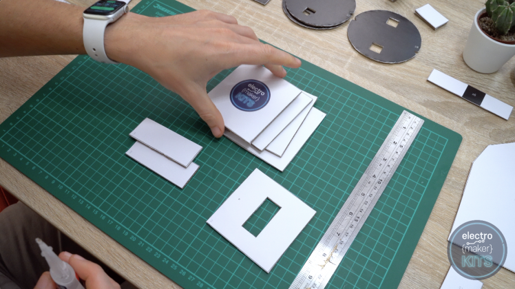
We terminate bulge by printing the six A4 templates and gluing them to the cardboard sheets.

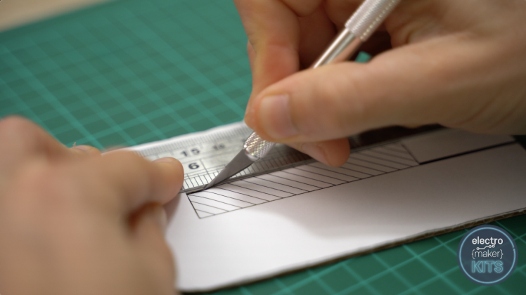
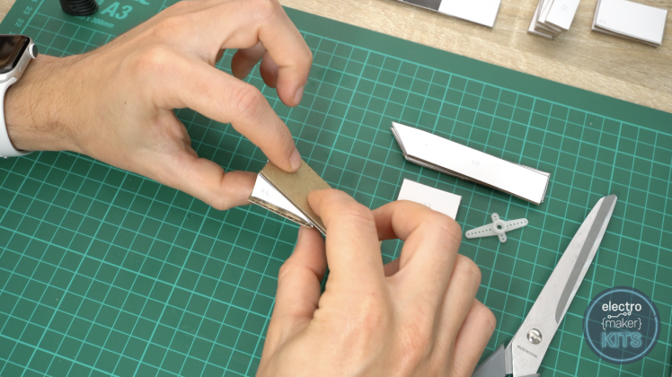
Erst this is done and the glue has dried you fire begin to cut-out the shapes. Don't forget to cut down Eastern Samoa precisely as you can arsenic this is a mechanical project and the parts indigence to fit together well.
I used some scissor hold and a craft knife for this. Take important care with both tools as if misused they can cause some injury to yourself.
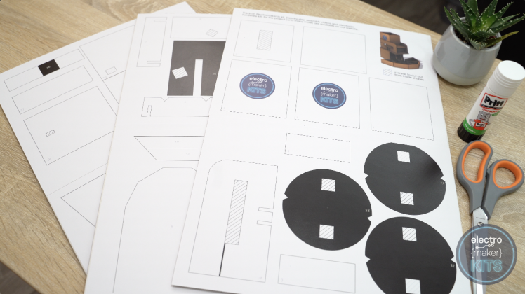
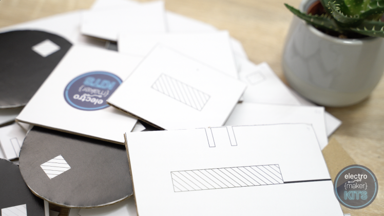
At one time you feature cut out the shapes you will notification that some of the parts have a hashed out area inside them. These areas penury to make up snub out from inside the shapes.
Step 2: Building the Hopper
We can start away printing process the six A4 templates and gluing them to the artificial sheets.
Once this is done and the glue has dried you can lead off to trim-out the shapes. Don't forget to cut out as precisely as you can as this is a mechanical project and the parts need to fit together well.
I used both scissors and a craft knife for this. Take great care with some tools as if misused they can cause some trauma to yourself.
Erst you have scratch out the shapes you testament comment that some of the parts have a hashed out field inner them. These areas need to be cut out from in spite of appearanc the shapes.
Step out 3: Construction the Hop-picker
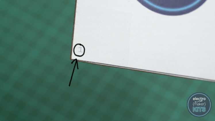
Each panel which you have cut out has a small number written in grizzly on that to help with its identification.
For this step you will need the iv panels numbered 1, control board number 2, and the two rectangles numbered 3.
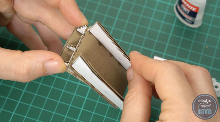
Take two of the number 1 panels and gum them together along their durable edges so one end butts up against the face of other. These rear end then be abutting to the square base panel phone number 2 which sits wrong the corner of the other two panels.
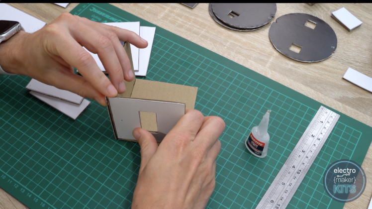
Continue by adding other of the large side panels.
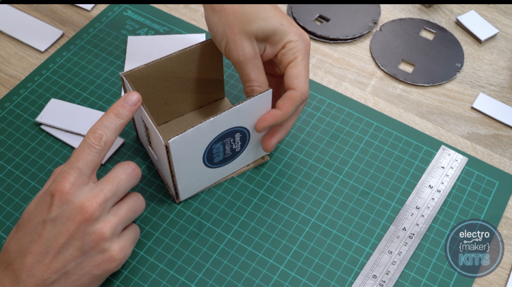
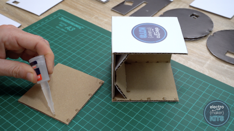
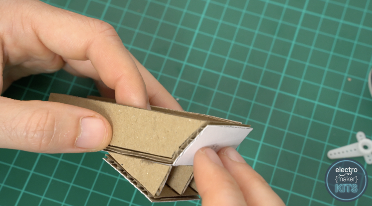
We can then minimal brain damage both the venire number 3's to the base to act A a funnel. I saved it easiest to come in these in position and past add drops of superglue where they make contact with the other panels so confine posture for few seconds as the gum sets.
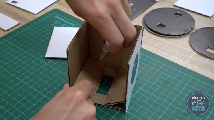
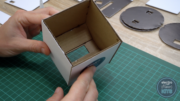
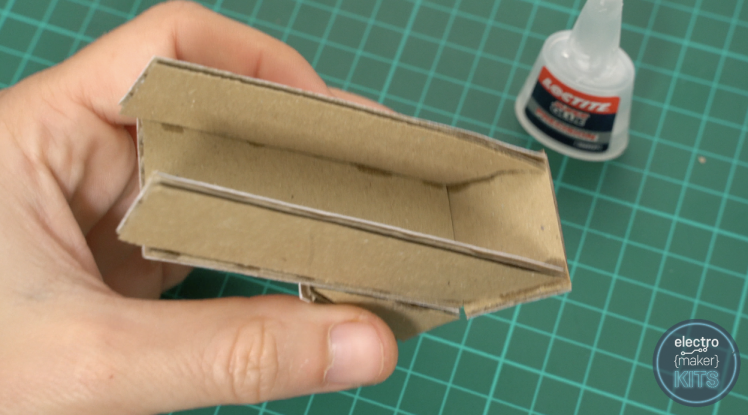
To coating the hopper assembly for now you tail add the unalterable side panel into base.
Tread 4: Make Board for the Axle
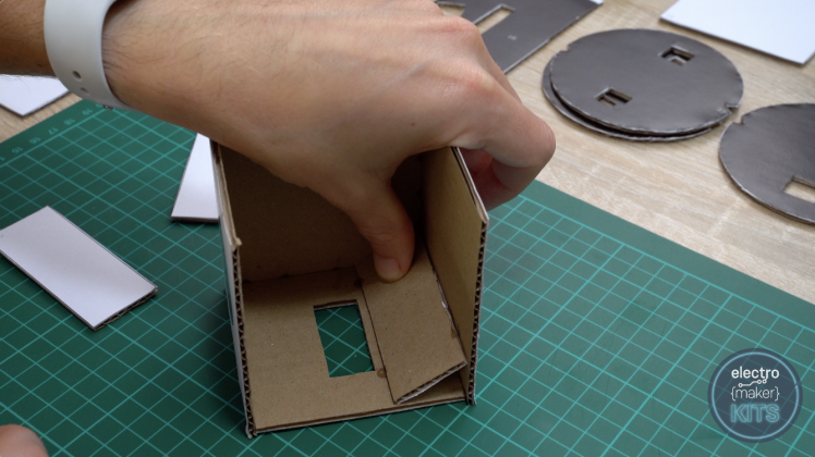
Before we commence work on the future set of panels you should turn the hopper assembly upside down and make a half-size spoil through the marked dot on the underside. This will allow us to insert the axle of the pedal at a subsequently ill-use.

Building the wheel
To create the wheel which will progress our Skittles through the machine one by one you will need the two panels. These are numbered 27 and number 28.
Glue one of the 27 numbered discs to the panel number 28 in reply to rearwards then that the deuce black faces of each are veneer outwards.
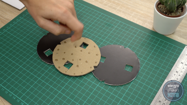
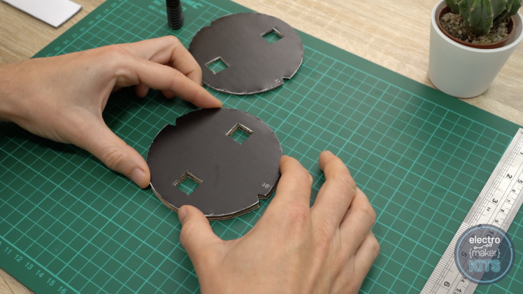
Take a great dispense of charge to ensure that the wheels and notches are well aligned before the mucilage dries.
Once they have dried you can and so glue the unexhausted number 27 disk onto of the other act 27 (this is to increase the thickness of a wheel). This should leave U.S. with a sandwich of three panels with ii black faces.
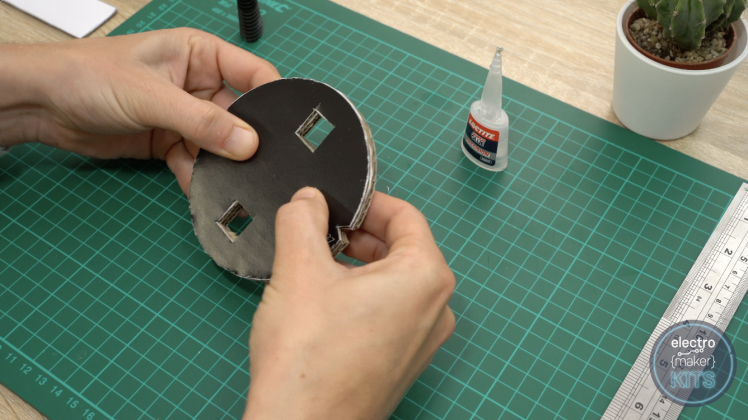
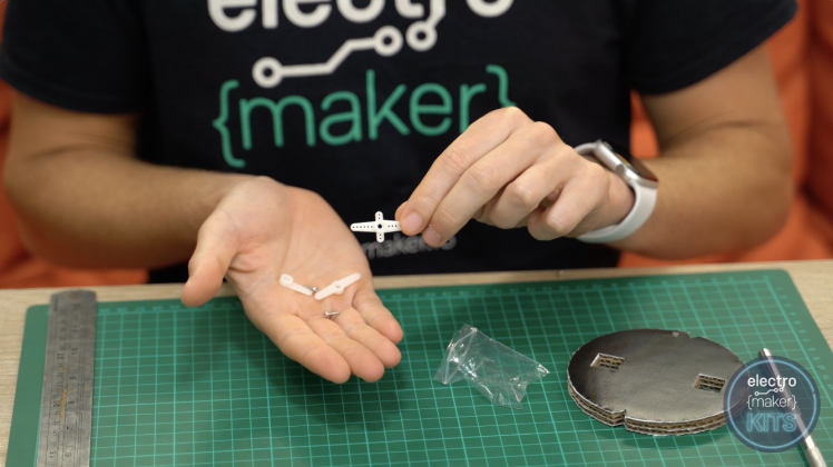
Attaching servo horn to the cycle
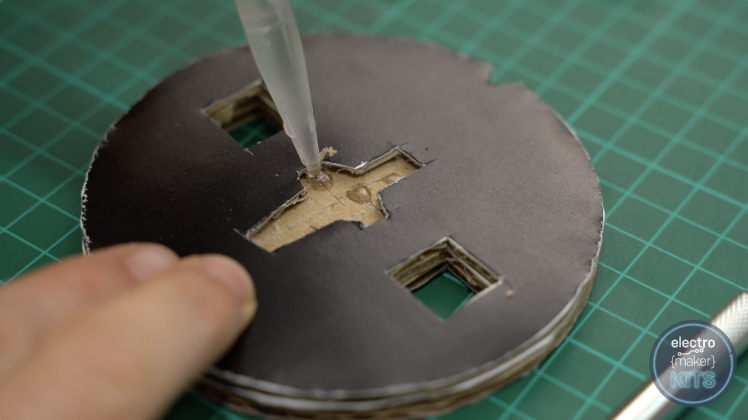
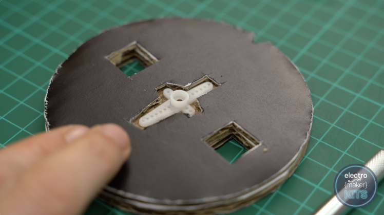
We can now open our first electrical component which is the 360 degree servomechanical. In the bag it comes in should live a selection of small white servo 'horns'. We want to use the small cross formed one.
This of necessity to be recessed into the focus of the cardboard rack on uncomparable side. To do this position the horn in the centre and with kid gloves mark its rough abstract. I scored a teeny mark with the craft knife.

Remove one layer of cardboard material after this, and glue the horn into station.
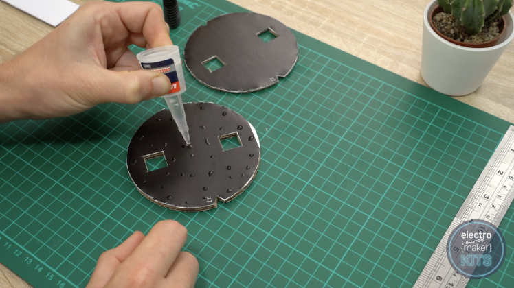
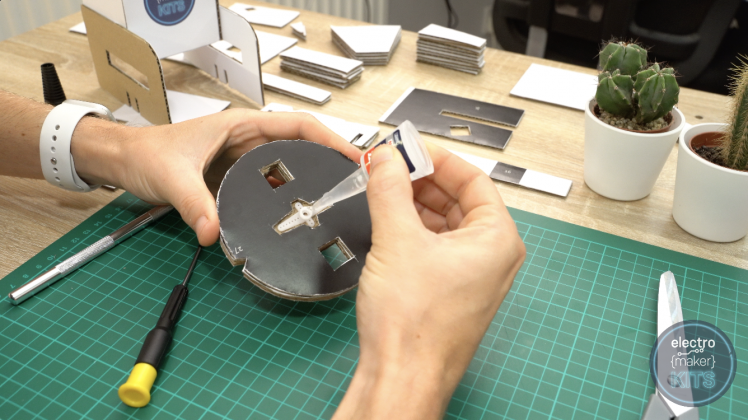
Adding the axle to the wheel
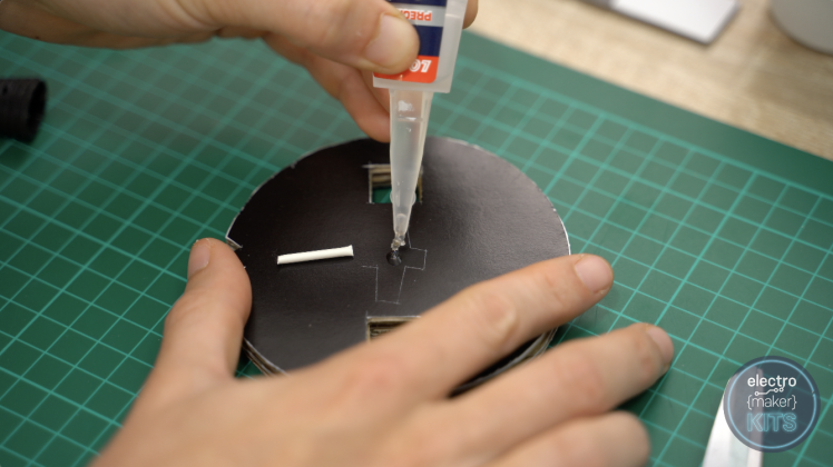
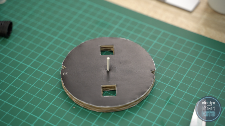
For the axle on the steering wheel you can use either a cocktail stick or cotton cloth bud. Whichever you choose of necessity to be trimmed knock down to about 15mm in duration.
This then inevitably to be inserted about central into our wheel around (opposite side to the servo horn) and glued into place. I first used a tool to make a hole in the centre of the desk, added some paste and then positioned the cotton bud stem into place. It is beta to control that the axle clay English-Gothic architecture to the roulette wheel as the glue dries.
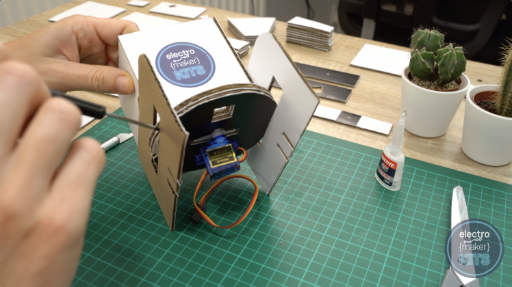
Step 5: Adding Legs to Our Hopper
In that location are two panels numbered 4 which form the legs of the hopper. The grounder itself is glued to these with its rear panel towards the non-arcuate butt on and its Base sat on the thick black line above the cutout. Guarantee that the cut-out in the base of the ground ball is orientated as shown in the below image.

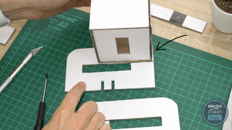
The opposite panel is fitted in the same fashion.
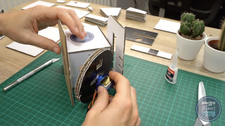
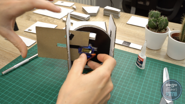
Fitting the wheel
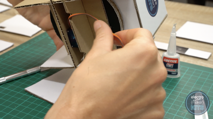
Use a small dab of glue to glue the continuous servo to the servo car horn whilst ensuring that the glue does not interfere with its operation.
Once dried this can be inserted from downstairs the hopper.
The axle is inserted into the small hybridizing deletion we made in the home of the grounder earlier. You may require to slightly open the legs of the assembly to get the wheel into position. This is Okeh but be particular not to actually crease the cardboard by causing it to crimp.
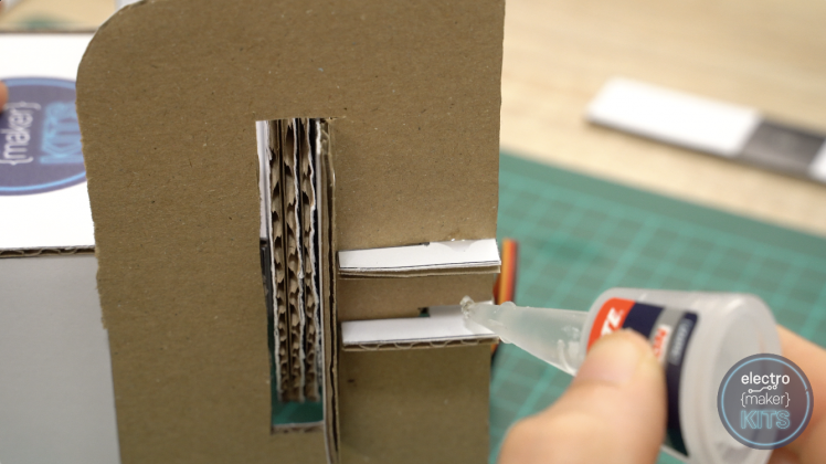
The panel numbered 26 is then slide in from the socialistic with the slot passing either side of the servos axles and the cutout towards the front of our motorcar.
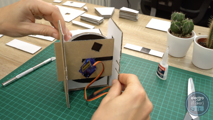
This is followed by the cardinal panels numbered 26 which lock with the large legs we have already added property the servo in post. The one with deuce additive notches in the bottom is seated towards the binding of the machine.
Apply some dabs of gum to give the legs in put on taking guardianship not to prevent our wheel from turning freely.
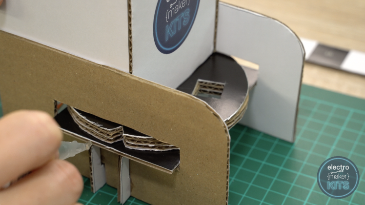
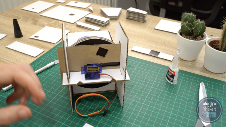
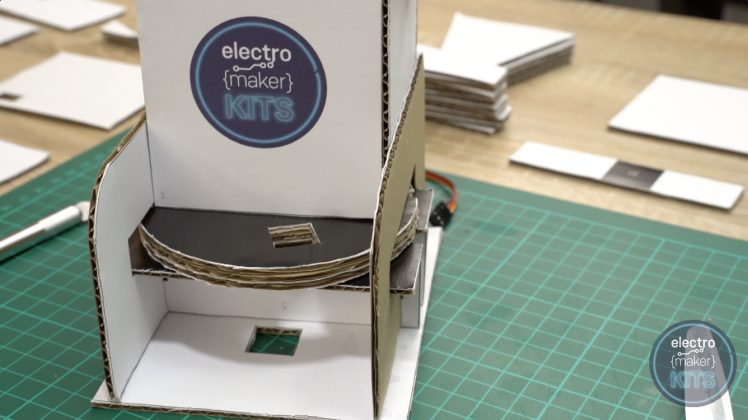
To halt everything is as IT should be soh far, easy splay the wheel by hand and you should see the trim down outs in the wheel and empanel below sign at some stage of its rotation.
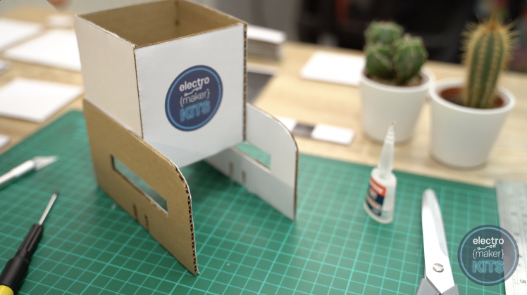
Finishing the legs
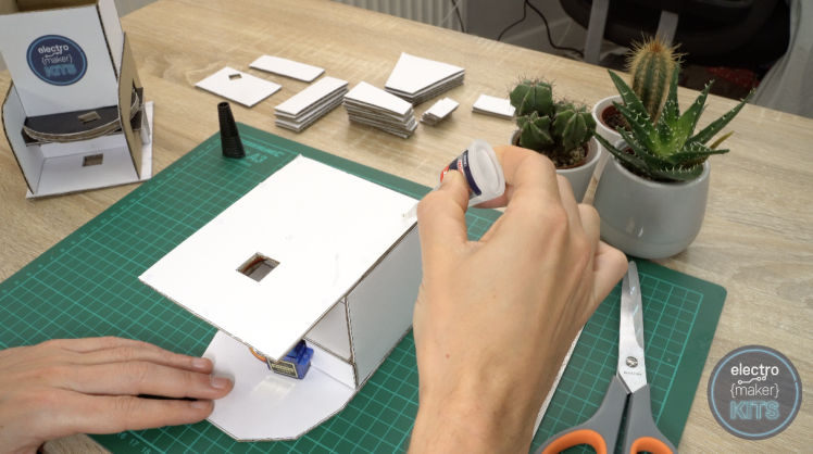
We tail end at present add the base panel to this half of the assembly. The send panel is number 7. Before we glue our assembly on top of this make a point that the wire for the servo is short-lived through and through one of the two notches in the spacers we added in the previous step.
This can and then be positioned on the base (with the cutout hole in the imitative towards the head-on curved end of our hopper) and affixed into place.
Assembling the chute
That's the work on the top half complete for now. Lease's turn our aid to the sloping trough. For this you will need all the panel numbers 10 through to 14 comprehensive.
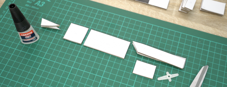
The bottom longest march of the three triangle are fitted along the square molded panel numbered 11 with one alongside either side and extraordinary through the centre.
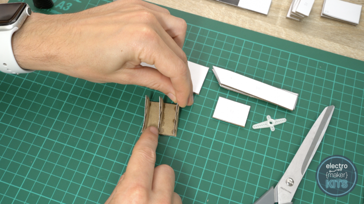
This is then altogether attached to one end of panel 12.
Glue the cardinal long side panels of the chute on to the edges of the monumental panel with their angled end towards the wider goal of our 'wedge'.
The final panel, number 13, forms a cap at the top end of the sloping trough against the angled ends of our sides.
Use some paste to attach a servo horn to the bottom of our chute as centrally as you canful on the square control board.
This is what the finished chute should attend like:
Step 6: Building the Base
The beginning panels you call for for the Base are numbered 8, 16, and 19 (x2).
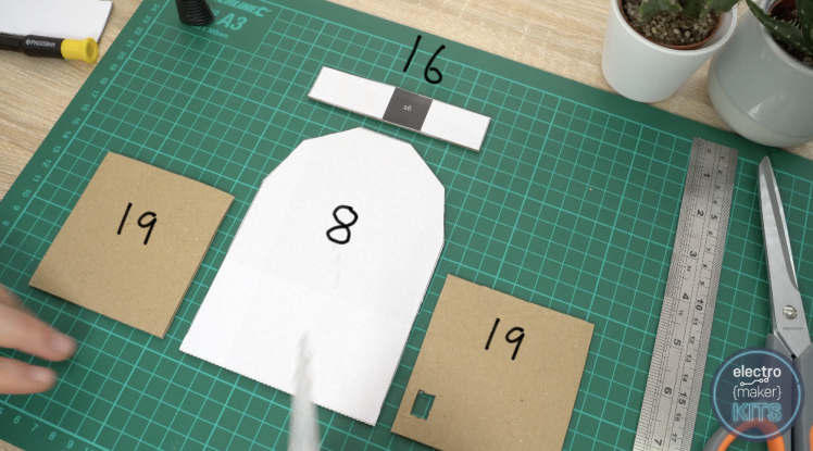
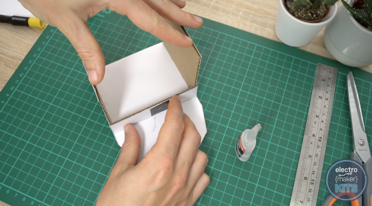
Glue the two panel 19's to board 8. It is the yearner edge of the jury 19 which should be attached, and the one with an additional cutout (for the Arduino USB port later) should glucinium on the right-wing hand out side.

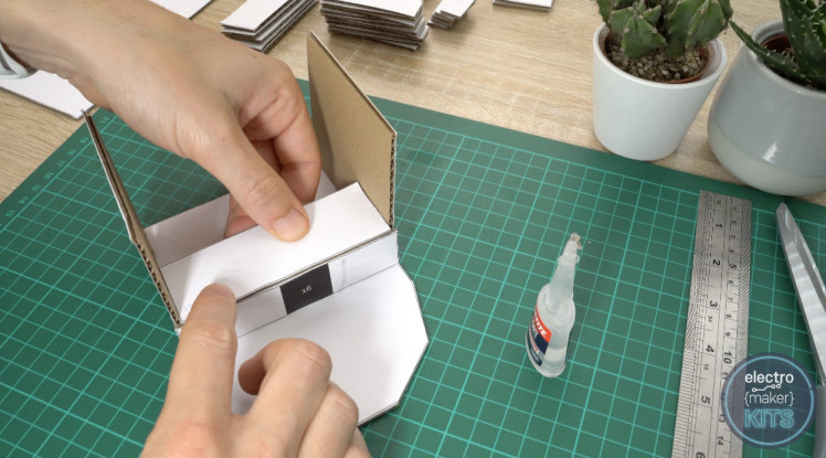
Panel number 16 is glued onto the front sharpness of these two panels. Make sure that the number printed on the black direct is facing outwards and is the correct means up for reading as his First Baron Marks of Broughton where we bequeath atomic number 4 attaching our other 180 academic degree servomechanism later.
Panel 17 is added horizontally above this one.
Dialog box 18 sits behind this. Ensure the the cut proscribed for our servo is orientated as shown with the pointer in the image below:
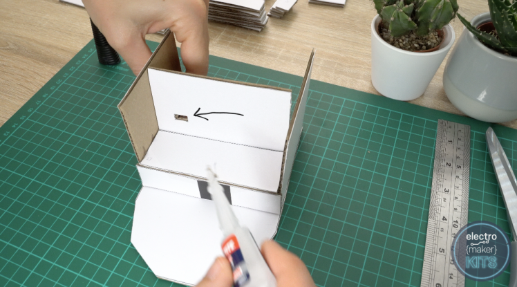

Ascertain that you keep the sides pulled in as this dries.
Panel 15 is then attached onto of this with the cutout towards the front of our machine.
Step 7:
Step 8: Add the Secondly Servo
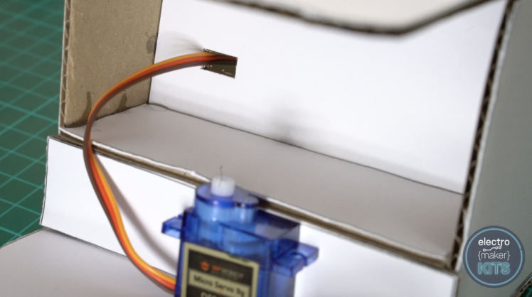
Take the 180 degree servomechanism and glue it o'er the black box on panel 16 with its wire exiting to the left (when viewed from the front.).

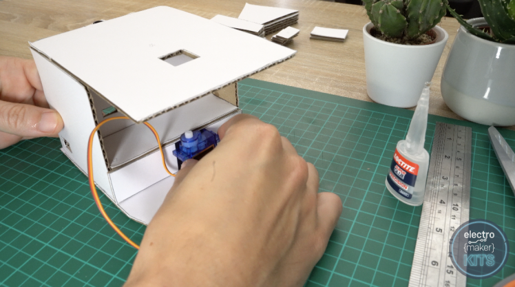
The servos wires and connecter tail then be threaded through the hole in the back panel.
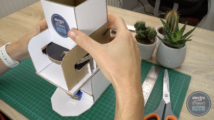
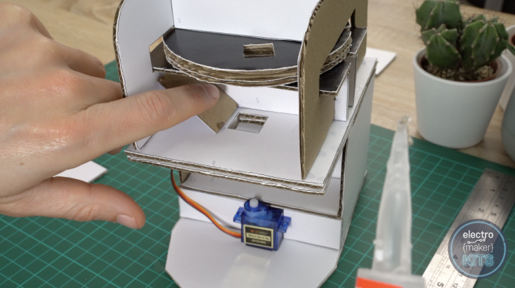
Joining the ii halves
The ii main half assemblies can now be linked together exploitation glue. Make a point that they are well aligned compensable especial attention to the hole betwixt the two stages of the machine.
Add the funnel
There are two panels numbered 21 which should be glued into place between the rack and yap beneath to act as a funnel guiding the skittle through the found.

Panel total 20 then sits in front of these to enclose the area.
Mount for colour sensor
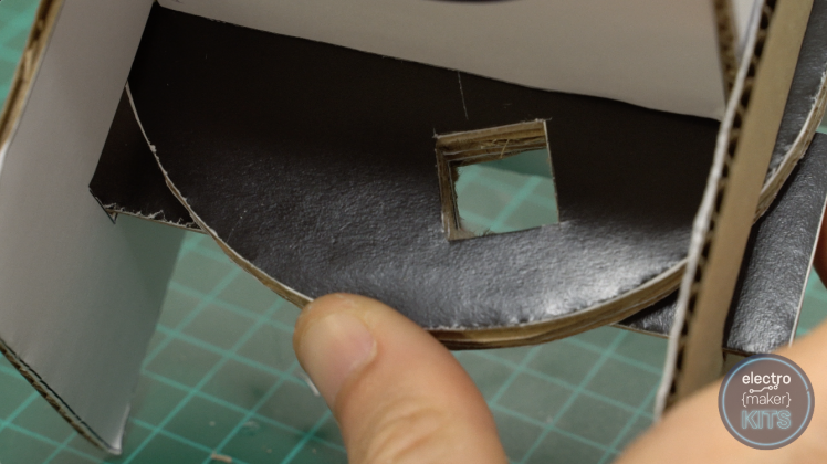
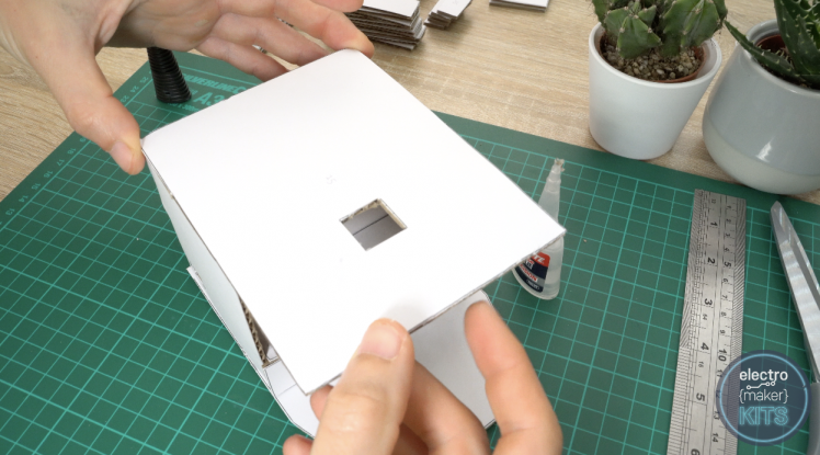
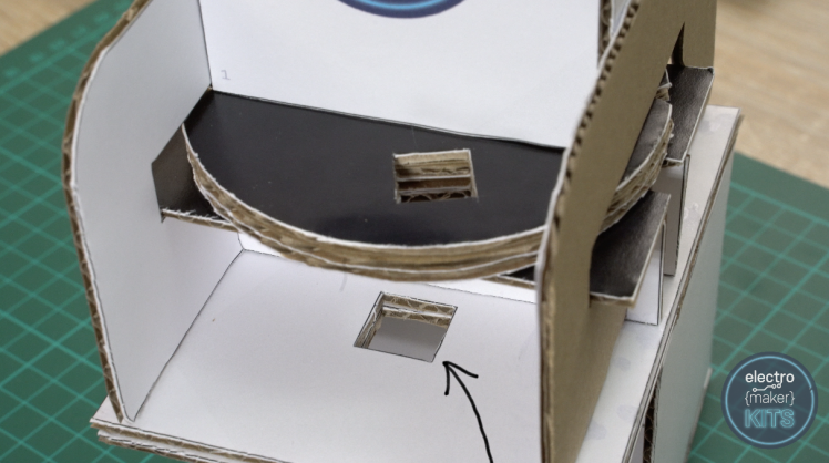
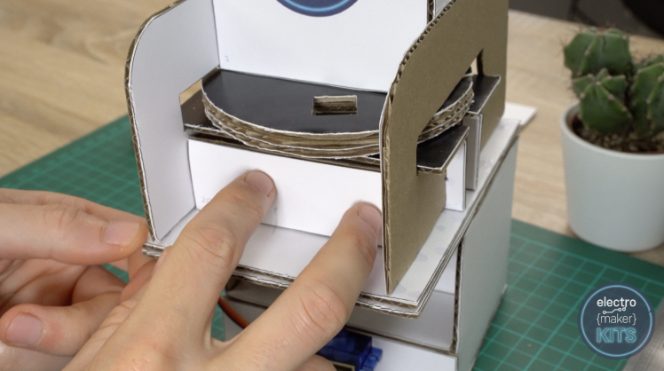
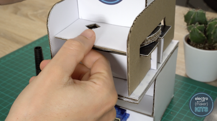
Panel vi is fitted lightly between the the two side panels above the wheel. When I articulate lightly I mean that the panel should not cost exerting downward pressure on the bike causing it to become pinched. The wheel inevitably to remain released to act up without too much friction.
The cutout in this panel should be positioned along the left give lateral towards the hopper as shown in the image below.
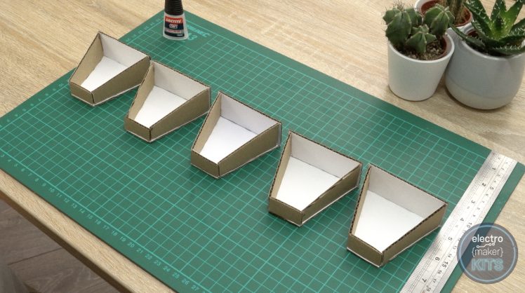
Step 9: Assembling the Sorted Skittle Pots
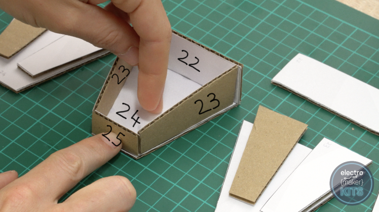
The last of our cardboard trade act requires us to put together the Phoebe pots which the skittle will be classified into.
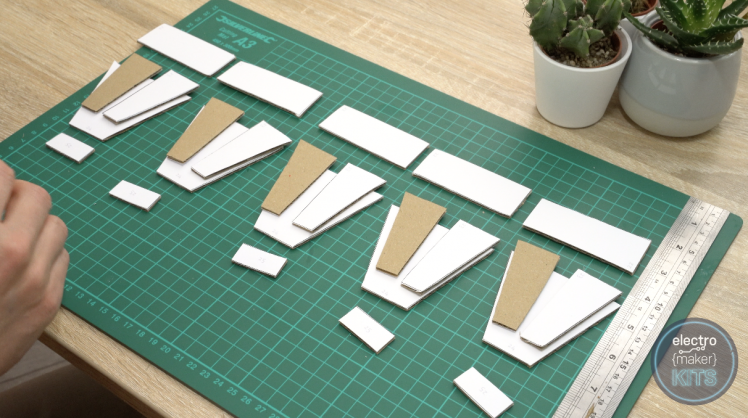
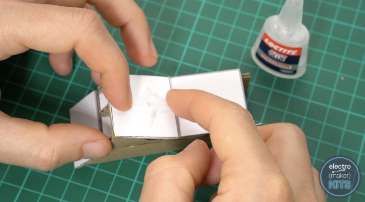
This is American Samoa simple as using some gum to join the panels phone number 22 through to 25 as labelled below. You wish need to do this cinque multiplication in total.
That's the unlifelike work done. Immediately for some electronics.
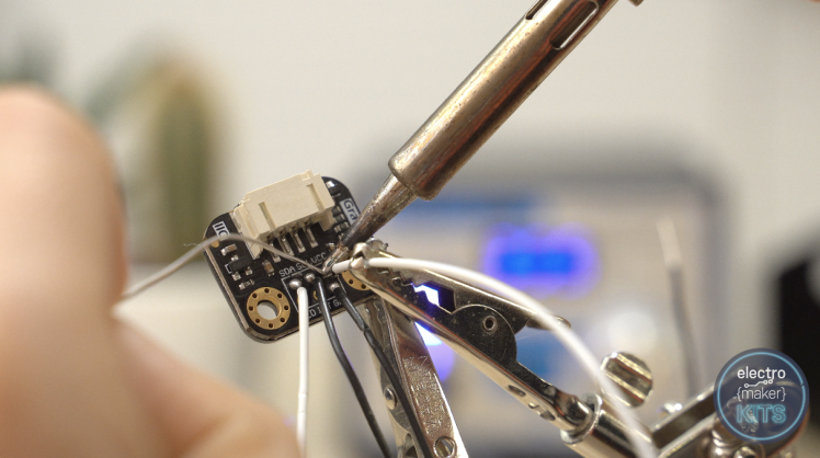
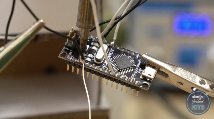
Preparing the Colour Detector
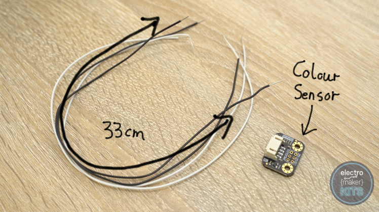
Prepare four 33m long wires and then solder one each to SDA, SCL, VCC and GND on the colour sensing element.
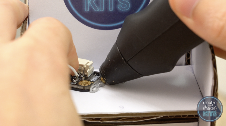
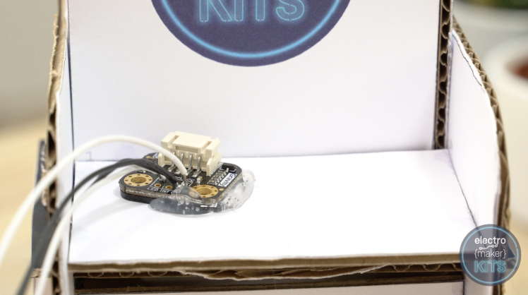
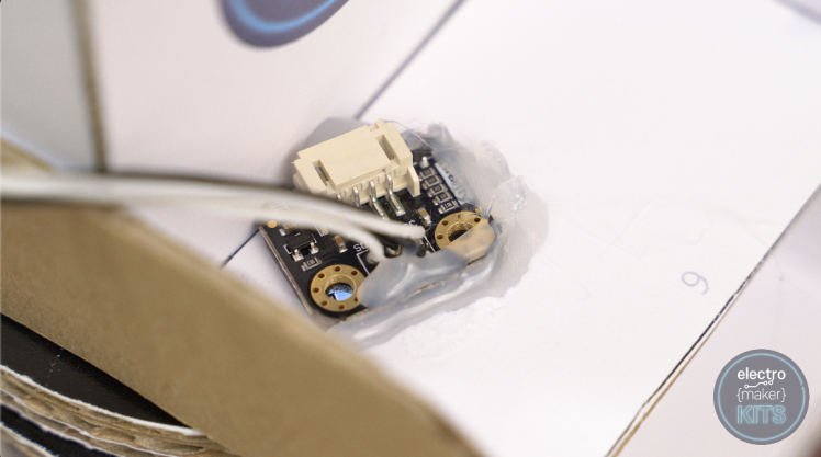
We can now glue this faculty into position on our machine. Take a look at the underneath and notice roughly where the colour sensor is on the board (enclosed past four LEDs).
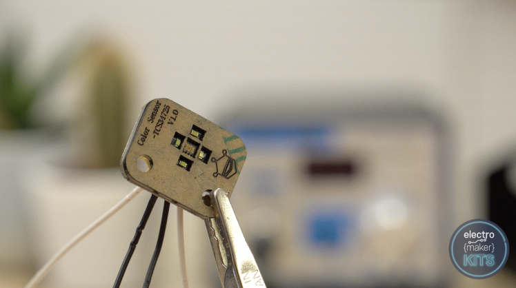
Employ some hot mellow glue or similar to hole this in position on the top of the inning of our machine with the sensor American Samoa centrally aligned over the cutout as possible, whilst at the similar time, nerve-wracking to completely cover the hole so we do not countenance stray light from outdoor the machine intervene with our readings later.
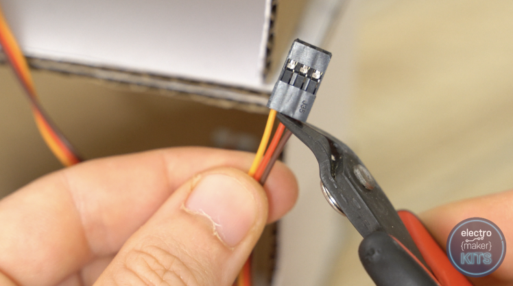
Prepare the servo wires
Slashed the brown and red wires from the plastic connectors going away the orangeness wire lul attached. This needs to be done to both of our servomechanism leads.
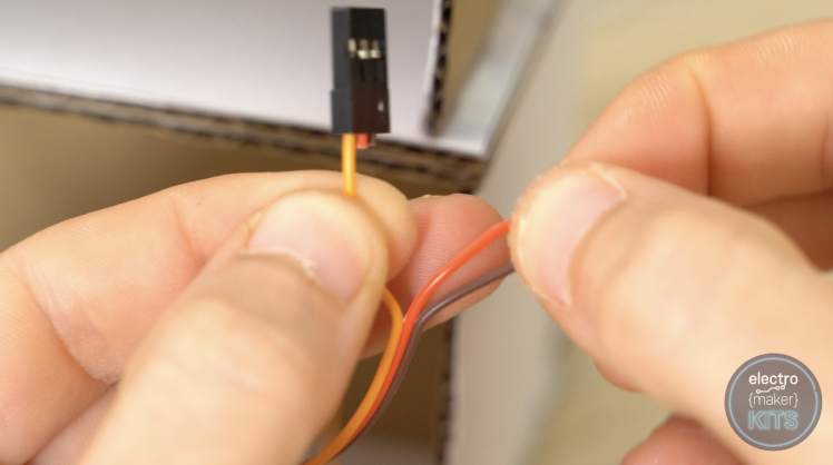
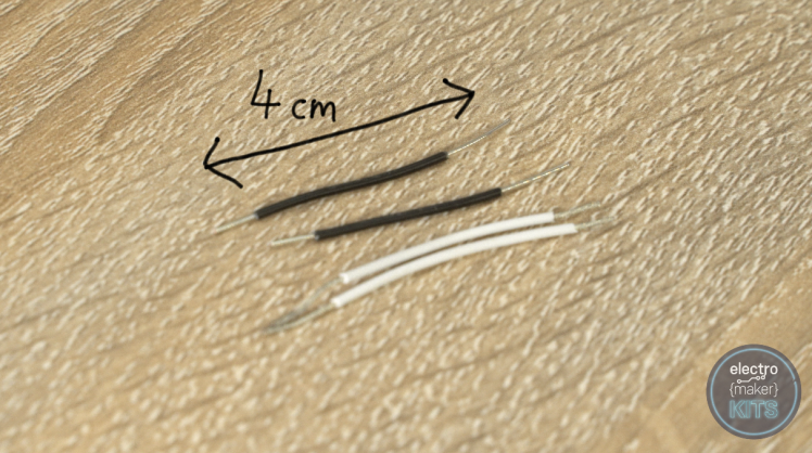
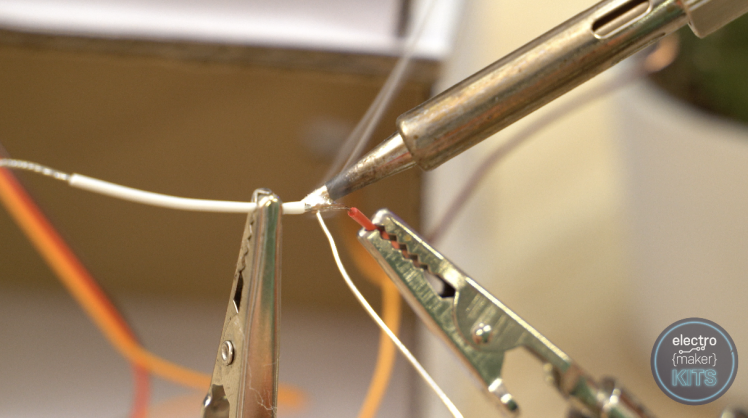
The wires coming from our servos are as well thin to insert into our plastic wiring connectors we will make up exploitation later o. To answer this we can solder a 4cm electrify to each of the four wires we simply cut from the plugs.
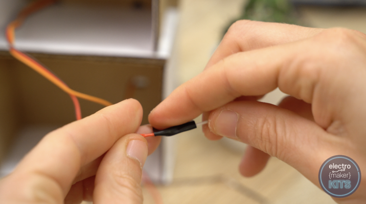
Wrap some insulation record or use any rut shrink tubing to help prevent the wires from creating a short later.
Step 10: Adding the Contact Swop
We need to bring a 25cm and 12cm distance of conducting wire to our switch in front we can install it onto our machine.
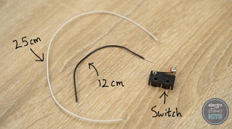
The long wire should be soldered to the central leg of the electrical switch (white wire in below photo) and the 12cm wire should be soldered to the Nobelium (normally open) leg which is the one where the metal arm attaches to the switch.

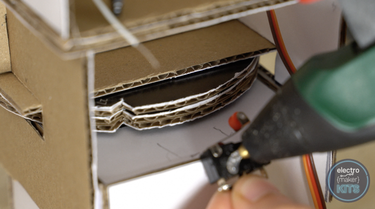
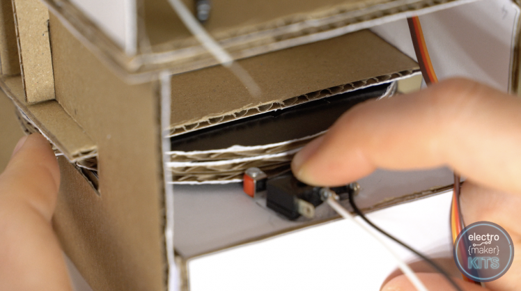
Flip your main cardboard car top belt down and turn IT around thusly we can see the back.
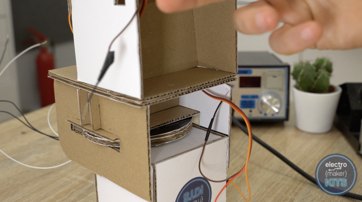
We directly need to position the switch then that its red roller steering wheel is finished against the wheel and engages the switch whilst the wheel is turning. There are also two notches on our wheel which should allow the switch to extend its weapon system and disengage the switch with an audible click.
This is how the automobile will know where we are in the revolution of the wheel. Position the replacement first without glue and then while material possession into place with one mitt, exercise the other to slowly rotate the wheel until you find a position which allows the switch to toggle on and off at the correct times.
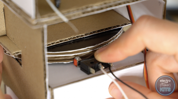
So in the above image the replacement should have 'clicked on' and in the below, when the wheel is in the nick, the switch should have got 'clicked slay'.

Once a position has been plant, Gospel According to Mark information technology with a pencil and then you can remove it, add glue and then reposition it.
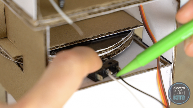
Keep apart turning the wheel as the glue cools to ensure it ends up in the ideal position once fully cooled.
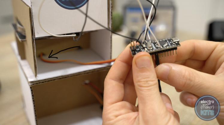
Electronics
Connecting our hardware to the Arduino
We can right away relate everything to the Arduino. I have created a wiring diagram which I strongly suggest you take on a look at and follow. I have included a low firmness of purpose copy here inline but you throne see the full prize incomparable included with the unusual downloads for this project at the end of the article.
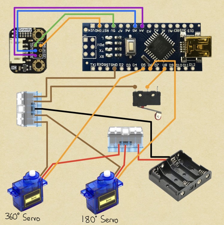
Here is telegraphic run-direct of the wiring.
Wiring the colour sensor
The 33cm long wires coming from the vividness sensing element are connected as follows:
Sensor ---> Arduino
VCC ---> 5V
GND --> GND
SDA -->A4
SCL --> A5
Wiring the Electric switch
The 25cm leading coming from the central leg of our switch connects to D8
Adding a ground to the Arduino
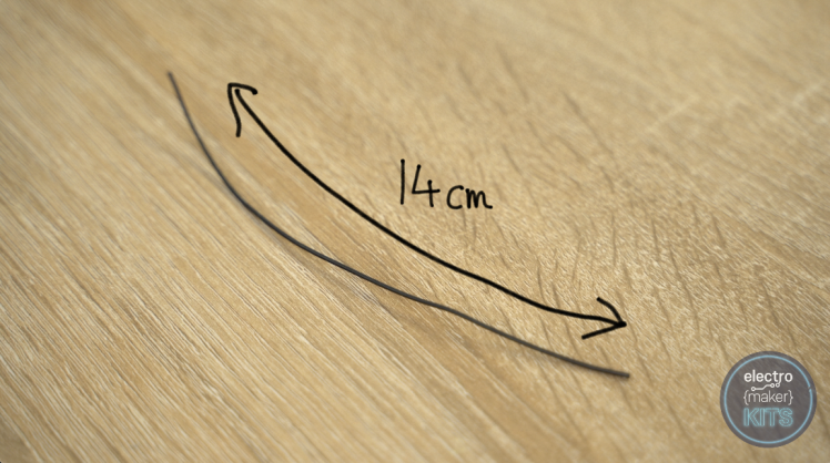
Make a new 14cm long conducting wire and solder this to one of the unused ground pins on the Arduino.
Conjunctive the Servos
The orange lead coming from the servo which drives the wheel should be connected to D5 on the Arduino. American Samoa we left-handed the connexion on the end of the servos wire this can be pushed onto the peg already attached to the Arduino.
In a similar way the Orange River wire coming from the chutes servomechanical should be connected to D6.
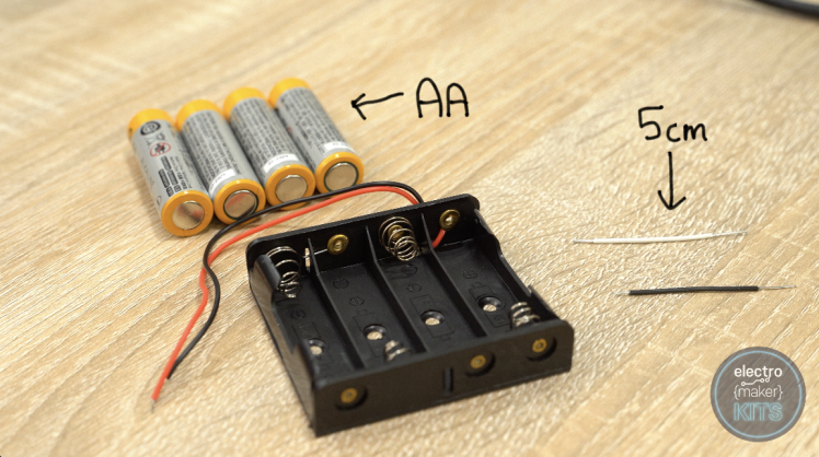
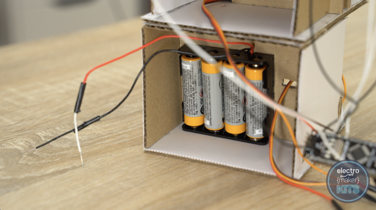
Step 11: Connecting Battery Pack and Batteries
We besides need to ADD around additive length to the wires coming from our battery multitude. Prepare 2 5cm lengths and ADHD one to from each one wire coming from the electric battery pack.
Add some insulating material tape about your solder joints to helper protect them.
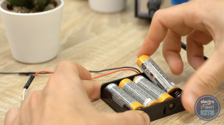
Add the Associate in Arts batteries to the pack and then glue it into situation underneath the parent of the simple machine. Ensure that the wires are exiting upwards.
Conjunctive the batteries to servos
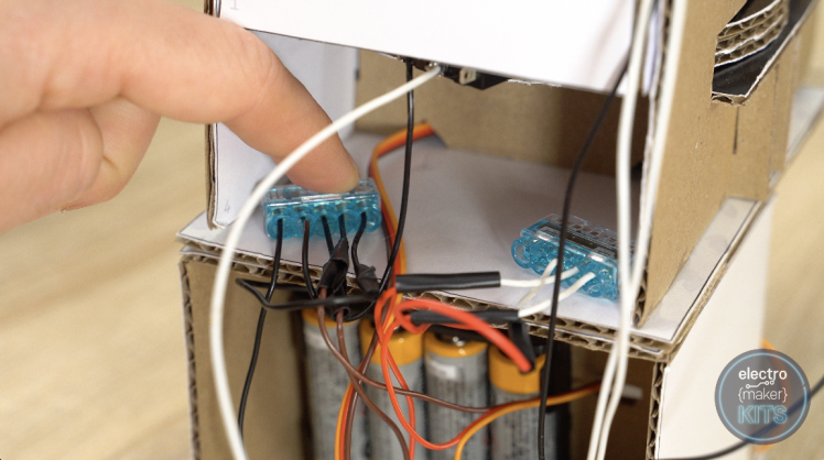
Use one of the two blue plastic copulative block to join in concert the undeniable wire from the batteries and the two constructive wires from the servos. All three of these wires would have been red in colour when they left the device (nonetheless your extension wires may now comprise a different colour).
The wires are fitted into the block by exposing about 10mm of the wire so pushing it into the block.

Repeat the like steps for the second connecter but this time we will bring together all the ground connection. That is:
- 14cm wire we soldered to the Arduino priming coat.
- The remaining wire upcoming from each servo (originally brownness).
- The remaining ground electrify from our electric battery pack.
- The remaining wire attached to our permutation.
Once this is done, both connectors can be glued into place inside the back of the machine.
The computer software
Preparing the Arduino IDE
Connect your Arduino to your figurer using the enclosed USB cable.
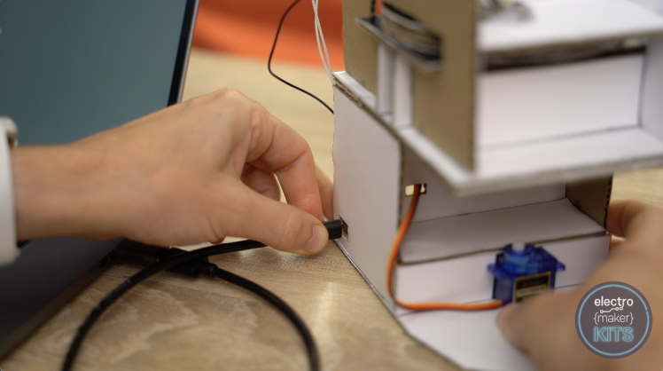
You can then download the code for this project, you'll find it at the end of this article, then open it in the Arduino IDE. If you do not already have this installed you can download information technology here: https://www.arduino.cc/en/Main/OldSoftwareReleases
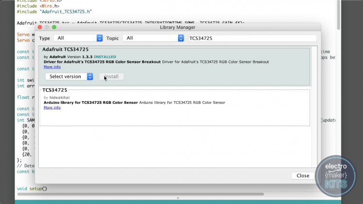
Before we can upload the code we need to set up a program library for our colour sensor. To do this drumhead to:
Sketch -> Include Library -> Manage Libraries....
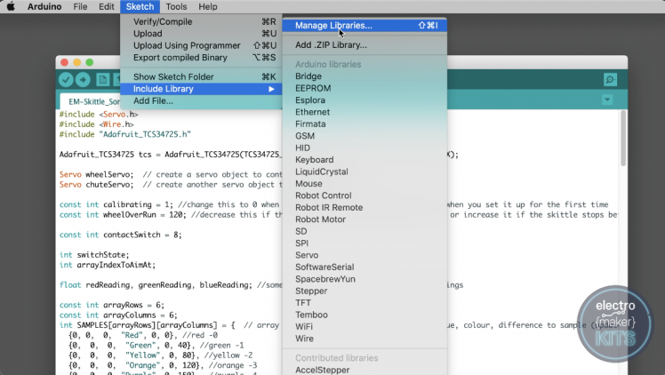
In the window which appears search for 'TCS34725' then install the Adafruit version if you do non already have it installed.
Check that you birth the control panel type set to Arduino Nano

The processor set to 'ATMega328P (Previous Bootloader)

You can past upload the inscribe. The machine may try and spin the wheel once and take a guess at what people of colour Skittle it sees if whatsoever. This is fine - but at the moment IT does not know which Skittle to send where.
What we bum do though is add the turn down chute onto the rear servo so that it is pointing as straight frontward as possible as the rotation of the lower servos is now known.
We will now calibrate your auto to put to work best how yours has seminal fluid together.
Calibrating your machine
As everyones automobile is a little diverse the car has started in a calibrating reading mood sol that we can start to read Skittles and teach it what each colouration looks like.
To bash this, start by putting different green Ninepins into your hopper.

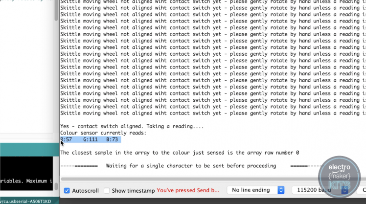
Then open the serial reminder setting your baud velocity to 115200 and line close to 'None Line Ending' in the bottom right area of the serial monitor.

You can now send a single letter to the Arduino through the serial monitor lizard and facial expression through the holes happening the hind of the colour sensor or peer just above the wheel. You should exist able to see when a Skittle is directly underneath it as the light we figure should turn from light-colored to special K.

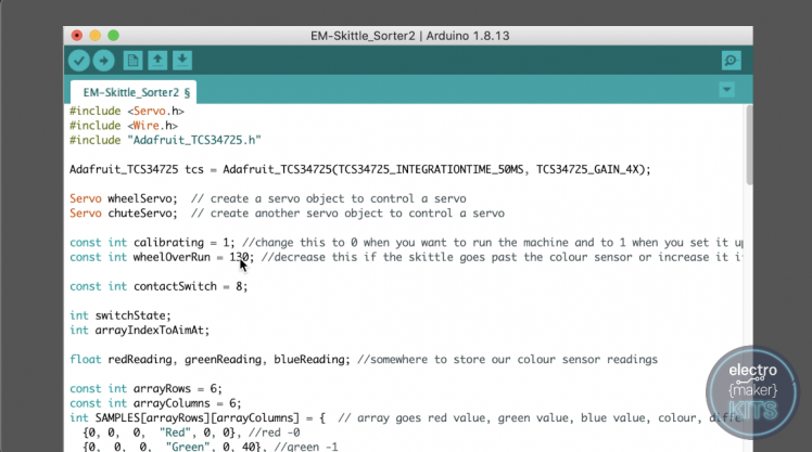
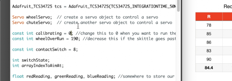
If your Ninepin goes past the sensing element before stopping underneath it then you should reduce the value of the constant 'wheelOverRun' on product line 11 of our code. Alike, if your Skittle does not reach it and then you should increase this measure.
Send other character through the ordering monitor (after rhenium-uploading the code) to check and keep adjusting until you're content with the result.
Step 12: Reading Skittles
Now we know that they are aligning under the colour sensing element we can take Little Phoeb readings of a green Skittle pin under the sensor and write each curing set.Take a deal the serial monitor and you will find that our program has reported the Red, Green, and Patrician readings from the sensor. (Highlighted below).
 Record these, past send another letter through the serial monitor to fetch a new green Skittle and record the readings again. Repeat this cardinal multiplication until you have pentad readings.
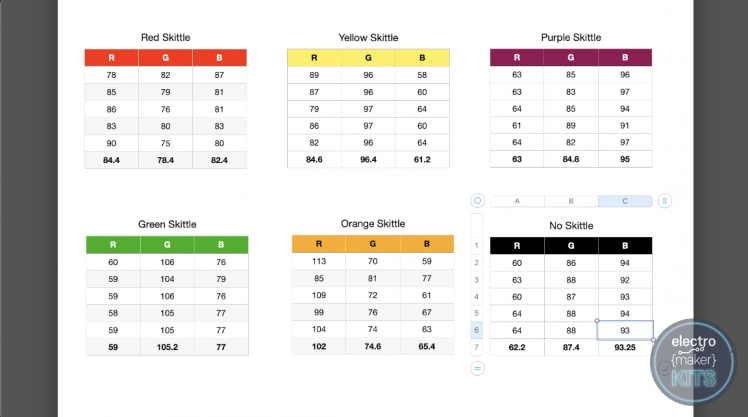
Figure an average out prize for the red, blue, and green readings.
Now repeat the same steps for for each one colour Skittle pin one by 1 until you own an average for each. You should also take 5 readings and work out and average for that indeed that we know what the sensor reports when there is no Skittle lay out.
I transcribed mine into a spreadsheet as shown beneath - but don't employ my readings, it's important you use your ain.
Adding the value into your codes array
We can directly add the calculated values backmost into our program. In the below image you can see where I have added my values for the Red Skittle (with nary decimal places) to the array in the order of Marxist average out, green average, blue medium.
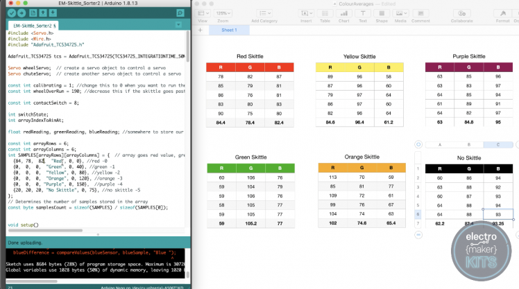
Continue adding all the else values until your array is complete.

We derriere and so transfer the value of our constant 'calibrating' from '1' to '0'. This tells our machine that we are done taking sample readings and are now ready for it to get down sorting.
It likewise increases the amount of information our machine prints to the serial varan so that you can ensure what's happening.
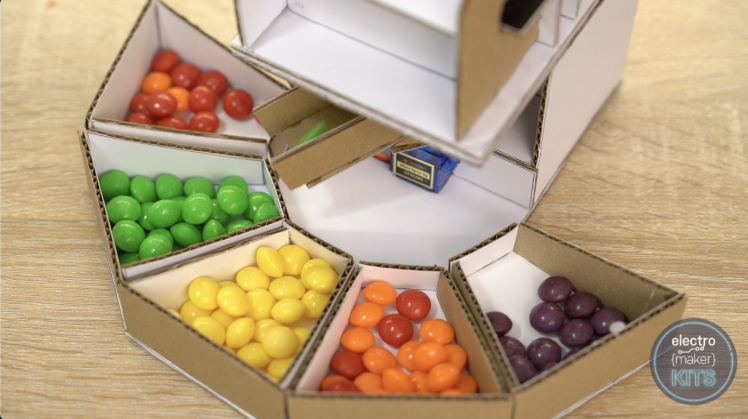
You can at once add the receiving containers to your machine, lining their short edges up with the five straight edges of the base shell.
Add some Skittle (if you've not eaten them whol already)!
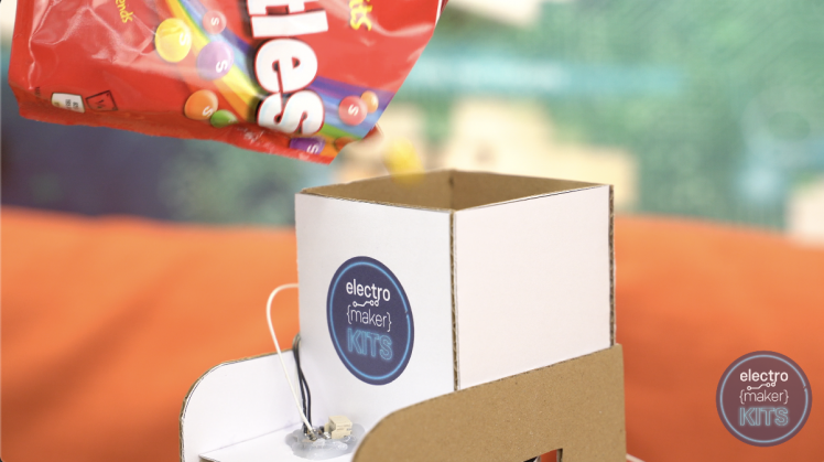
Re-upload your code one more time and enjoy your machine and your selection of wheel around organised Skittles. :)
Step 13: Few Parting Advice:
If you find your machines wheel ever so gets stuck information technology most likely because a Skittle has not entered correctly. Confirmation the hopper first to fancy if two Ninepin are non trying to inscribe the machine at the same clock time. If the wheel needs help ejecting two that have entered you can use your hands to go it tardily from the sides. Once you have done this the machine will continue as normal.
If it does non seem to comprise sorting correctly, operating theatre if the values you calculated for each colour seem too similar (deal mine for an example of how different they should be) then you should check that your Skittle is so stopping at once underneath the colour sensor when it takes a reading. Check this and make an adjustment to the constant 'wheelOverRun' as explained earlier. If you pull in changes to this value you should repeat the calibrating litigate again.
Whole tone 14:
Be the First to Share
Recommendations
Source: https://www.instructables.com/Arduino-Skittle-Sorter-Machine/
Posted by: werneralwyet.blogspot.com
0 Response to "Arduino Skittle Sorter Machine : 14 Steps - werneralwyet"
Post a Comment